Mechanical fabrication projects require more than a design concept or a general arrangement drawing. Fabricators need detailed documentation that explains how each component should be manufactured, inspected, and assembled. For U.S. manufacturers, fabricators, and engineering teams, mechanical shop drawings provide a practical connection between engineering intent and production requirements. They communicate dimensions, materials, manufacturing details, and other information needed to produce components accurately.
Well-prepared drawings also help different teams work from the same technical information. When dimensions, specifications, and assembly details are coordinated, fabricators can identify potential issues before production begins. This guide explains what mechanical shop drawings should include, why each detail matters, common documentation problems, and how professional CAD drafting support can help prepare consistent fabrication documentation.
What Are Mechanical Shop Drawings?
Mechanical shop drawings are detailed technical drawings used to communicate how mechanical components, assemblies, or fabricated products should be manufactured. They translate engineering designs into practical information that fabricators, machinists, welders, and assembly teams can use during production. For example, a fabricated metal frame may require drawings showing its overall dimensions, individual members, material specifications, connection details, and assembly arrangement.
The exact drawing requirements depend on the component, manufacturing process, project specifications, and information provided by the engineering team. When manufacturers need help preparing or updating these documents, professional mechanical drafting services can provide additional CAD drafting and documentation support.
What Should Mechanical Shop Drawings Include?
There is no single checklist that applies to every mechanical fabrication project. However, professional shop drawings commonly include several core elements.
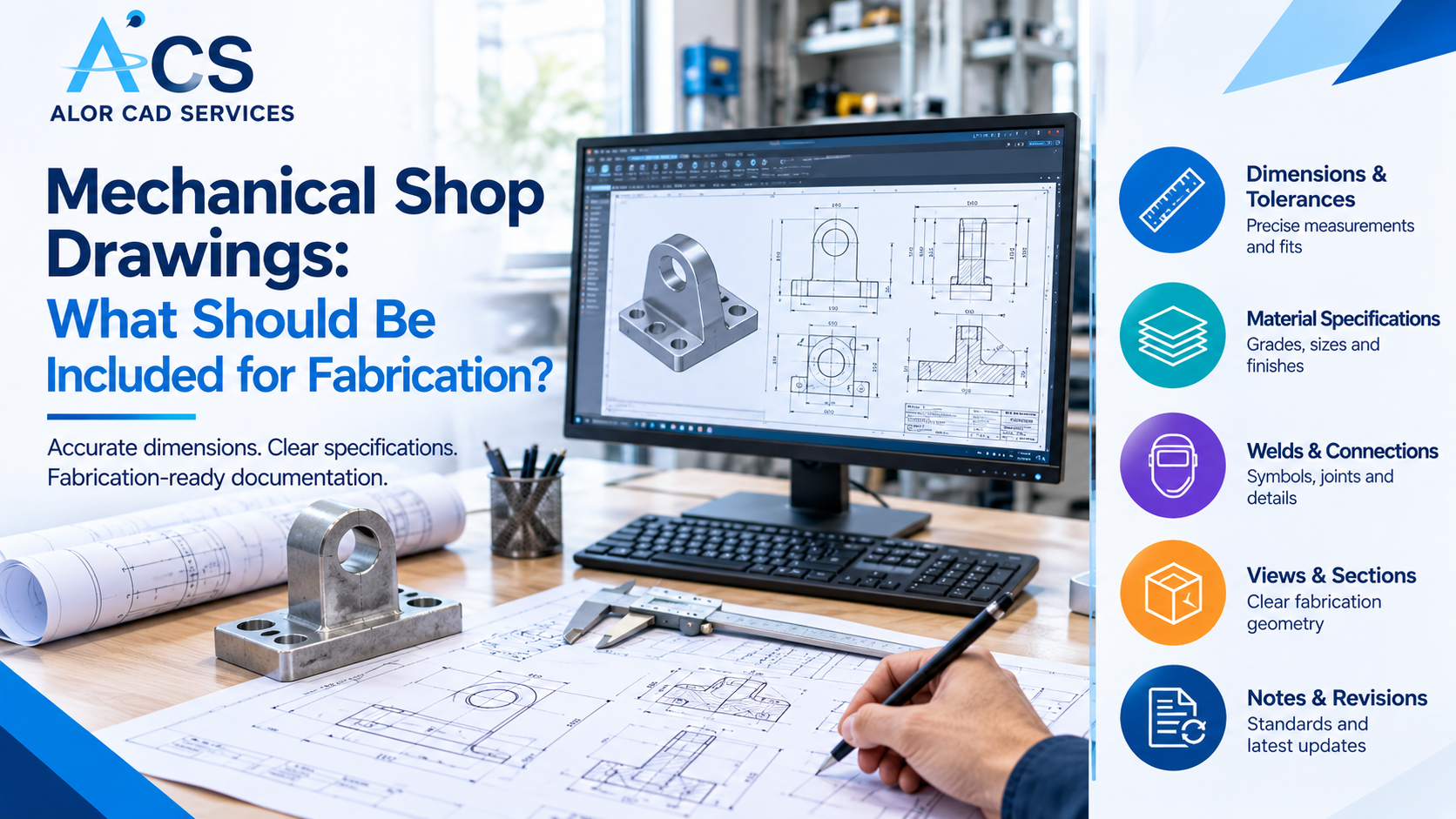
Dimensions and Geometric Details
Dimensions communicate the required size, shape, and position of each component. They help fabricators understand how a part should be manufactured and how it relates to other components in an assembly.
A fabrication drawing may include:
- Overall length, width, and height
- Hole diameters and center-to-center distances
- Plate thicknesses and material profiles
- Angles, radii, and bend dimensions
- Slot locations and cutout dimensions
- Reference dimensions and other relevant measurements
Dimensions should be clear, complete, and consistent across the drawing package. Critical dimensions should be identified so that production and inspection teams understand which measurements require particular attention.
Material Specifications
Material information helps fabricators select the correct stock and understand the requirements for manufacturing each component. A drawing may identify the material grade, type, thickness, or other specifications relevant to the project. For example, a component may require a particular steel grade, aluminum alloy, or specified plate thickness.
Material information should match the approved engineering design and applicable project documentation. When additional material requirements apply, such as surface finish or heat treatment, the drawing should identify those requirements or reference the appropriate specification.
Tolerances and Fit Requirements
Tolerances define the acceptable variation in dimensions and other geometric characteristics. Manufacturing processes naturally involve some variation. Clearly defined tolerances help fabricators understand how much variation is permitted without affecting the component’s intended function.
Mechanical shop drawings may include:
- Linear and angular tolerances
- Hole and shaft fit requirements
- Geometric tolerances where specified
- Surface finish requirements
- Critical interface dimensions
Tolerances should reflect the engineering requirements and the intended function of the component. Applying unnecessarily tight tolerances can increase manufacturing difficulty and cost. Missing tolerances, on the other hand, can leave important production requirements unclear. For projects requiring geometric dimensioning and tolerancing (GD&T), the applicable drawing standards and engineering requirements should guide the presentation of these details.
Welding and Connection Details
For welded or connected assemblies, shop drawings should communicate how the individual components are joined. Depending on the project, this information may include weld symbols, weld locations, connection dimensions, and applicable welding requirements. Drawings may also show bolted connections, fastener specifications, and other mechanical joining details.
Connection information should be coordinated with the overall assembly design so that fabricators can understand how the components fit together. Where welding procedures, inspection requirements, or other supporting documentation are needed, the drawings should reference the applicable project specifications.
Manufacturing and Fabrication Details
Fabrication drawings should provide the information required to produce each component using the intended manufacturing process. Depending on the part, this may include machining details, cutting information, bend dimensions, hole patterns, and other manufacturing requirements. For sheet metal components, drawings may need to communicate material thickness, bend angles, bend locations, and other relevant features.
Machined components may require additional information about holes, threads, surface finishes, and critical dimensions. The drawing should provide sufficient detail for the intended manufacturing process without introducing unnecessary information that could create confusion.
Assembly Drawings and Bill of Materials
Assembly drawings explain how individual components fit together to form a complete product or mechanical system. They may show the overall arrangement, component positions, connection points, and assembly sequence where relevant. A bill of materials (BOM) can support the assembly drawing by identifying the components required for the assembly.
A typical BOM may include:
- Item numbers
- Component descriptions
- Part numbers
- Required quantities
- Material information where applicable
Item numbers on the assembly drawing should correspond to the BOM so that fabricators and assembly teams can identify the correct parts.
Drawing Notes and Revision Information
General notes and drawing references communicate requirements that may not be practical to show through dimensions alone. These notes may address manufacturing instructions, finishing requirements, inspection details, or references to other technical documents. Revision information is also important when drawings change during a project.
A drawing should identify its revision status and provide the applicable information about approved changes. Clear revision control helps ensure that fabrication teams work from the correct documentation rather than outdated drawings.
Why Are Mechanical Shop Drawings Important for Fabrication?
Mechanical shop drawings help translate engineering requirements into information that production teams can follow. They provide a common technical reference for engineers, fabricators, machinists, inspectors, and assembly teams.
Accurate shop drawings can help:
- Communicate design intent
- Identify required materials and components
- Support manufacturing and assembly planning
- Clarify dimensions and tolerances
- Coordinate fabrication and inspection activities
- Reduce avoidable production errors
- Support consistent documentation across projects
How Do Shop Drawings for Manufacturing Differ From Production Drawings?
Shop drawings for manufacturing and production drawings both communicate technical information needed to manufacture components and assemblies. Shop drawings typically focus on fabrication details, dimensions, connections, and assembly requirements, while production drawings may include additional machining and inspection information. The required details depend on the project and manufacturing process, ensuring each team has the information needed to complete its work.
Common Problems With Mechanical Fabrication Drawings
Many fabrication issues begin with missing or conflicting drawing information rather than a major engineering problem.
Common documentation problems include:
- Missing or unclear dimensions
- Incorrect material specifications
- Inconsistent part numbers
- Missing weld or connection details
- Unclear tolerances
- Conflicting information between component and assembly drawings
- Missing finishing or manufacturing requirements
- Outdated drawing revisions
- Incomplete BOM information
Practical Considerations Before Preparing Mechanical Shop Drawings
The quality of fabrication documentation depends partly on the quality of the engineering information available during drafting. Before preparing shop drawings, project teams should collect and verify the relevant inputs.
These may include:
- Approved engineering drawings
- CAD models or other design information
- Component dimensions and material specifications
- Assembly requirements
- Manufacturing process information
- Applicable tolerances and finishing requirements
- Welding and connection specifications
- Inspection requirements where applicable
- Project-specific drawing standards
When information is missing or unclear, it should be identified for clarification rather than assumed during drafting. Collecting these inputs early can help reduce unnecessary revisions and improve coordination between engineering and fabrication teams.
How to Prepare Better Mechanical Shop Drawings for Fabrication
A structured drafting workflow can help manufacturers maintain consistent documentation across individual components and larger assemblies.
A practical workflow includes the following steps:
- Review the approved design information and project requirements.
- Identify the components and assemblies that require fabrication drawings.
- Collect and verify the required dimensions, materials, tolerances, and manufacturing details.
- Prepare component drawings with the necessary views and annotations.
- Create assembly drawings and BOM information where required.
- Coordinate dimensions, part numbers, specifications, and revision details.
- Review the drawing package for missing or conflicting information.
- Update the drawings based on approved engineering changes.
How CAD Support Can Help Fabrication Teams
Preparing and updating mechanical shop drawings can become time-consuming when manufacturers are managing multiple projects or handling frequent design changes. Professional CAD support can provide additional drafting capacity while allowing internal engineering teams to focus on design, production planning, and technical decision-making.
Mechanical CAD drafting support can include:
- Preparing detailed component drawings
- Creating mechanical assembly drawings
- Developing fabrication drawing packages
- Updating dimensions and manufacturing details
- Preparing BOM documentation
- Coordinating drawing revisions
- Converting existing design information into CAD drawings
- Maintaining consistency across related drawings
ALOR CAD Services for Mechanical Shop Drawings
ALOR CAD Services supports U.S. manufacturers, OEMs, fabricators, and engineering teams with mechanical drafting and technical documentation. Our mechanical drafting capabilities include shop drawings, fabrication drawings, machining drawings, sheet metal drawings, weldment drawings, and assembly drawings. For fabrication teams, coordinated drawings can provide a clearer reference for manufacturing, assembly, and technical review. Learn more about our mechanical drafting services and how ALOR CAD Services can support your fabrication documentation workflow.
Conclusion
Mechanical shop drawings translate engineering designs into fabrication-ready documentation. They include dimensions, materials, tolerances, and assembly details to support accurate manufacturing, reduce errors, and improve coordination. Requirements vary by project, so drawings should be based on verified engineering information and reviewed before fabrication. If your team needs support preparing or updating mechanical shop drawings, contact ALOR CAD Services to discuss your project requirements and CAD documentation needs.
Frequently Asked Questions
What are mechanical shop drawings used for?
Mechanical shop drawings communicate the dimensions, materials, manufacturing details, and assembly requirements needed to fabricate mechanical components and assemblies.
What information should fabrication drawings include?
Common information includes dimensions, material specifications, tolerances, manufacturing details, connection information, and revision details. Assembly drawings and BOMs may also be required.
Are mechanical shop drawings the same as production drawings?
Not always. Shop drawings often focus on fabrication and assembly details, while production drawings may include additional information used throughout manufacturing. The exact distinction depends on the project and organization.
Why are tolerances important in fabrication drawings?
Tolerances define acceptable variation in dimensions and other characteristics. They help fabricators understand the required accuracy and support proper component fit and function.
Can CAD companies help prepare fabrication shop drawings?
Yes. CAD service providers can support the preparation, coordination, and revision of mechanical fabrication drawings based on the engineering information and requirements provided.