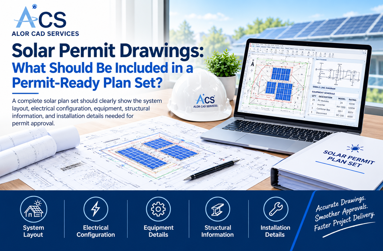
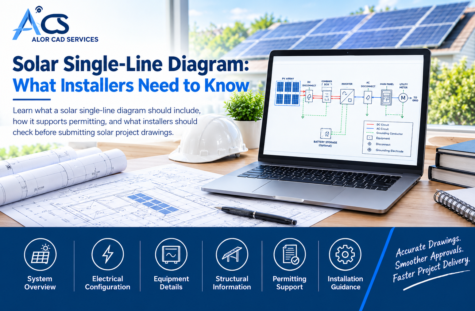
A well-prepared solar single-line diagram gives installers, permitting authorities, and other project teams a clear view of how a proposed PV system is connected electrically. For U.S. solar installers, accurate electrical documentation can help support the permitting and installation process. While the exact requirements vary by system type, equipment, utility, and local jurisdiction, a professional diagram typically communicates the major electrical components, connections, protection, and service information needed for review. For installers managing multiple projects, working with an experienced CAD and drafting partner can also help maintain consistency across project documentation.
What Is a Solar Single-Line Diagram?
A solar single-line diagram is a technical drawing that shows the main electrical connections within a proposed photovoltaic system. Rather than representing every physical wire separately, it uses simplified lines and symbols to show how the major components connect.
A typical drawing may include the PV array, inverter, disconnects, electrical panels, utility meter, grounding information, and other relevant equipment. Battery storage may also be included when the project uses an energy storage system.
The exact contents depend on the project. A residential system may require a simpler drawing than a larger commercial installation with multiple inverters, batteries, or more complex electrical equipment.
What Should a Solar Single-Line Diagram Include?
The contents of an electrical drawing depend on the proposed system and applicable review requirements. However, several types of information are commonly important when documenting a PV installation.
1. PV Array Information
The drawing should represent the solar array and provide enough information to understand how the PV modules are electrically arranged. Depending on the system, this may include the number of modules, string configuration, and connections leading toward the inverter or other equipment.
The information should correspond with the module layout and other project documents. If the number of modules shown in the electrical drawing differs from the roof layout, the reviewer may request clarification or revisions.
2. Inverter Information
The inverter is an important part of the electrical path because it converts DC power from the PV array into AC power. The diagram should identify the inverter and, where applicable, provide its manufacturer, model, quantity, and relevant electrical ratings.
The equipment information should match the actual equipment selected for the project. Changes made during the design process should also be reflected in the applicable drawings and schedules.
3. Disconnects and Electrical Equipment
A solar electrical drawing should identify the major equipment used to control, protect, and connect the PV system. Depending on the project, this may include:
- DC and AC disconnects
- Combiner equipment
- Electrical panels
- Main service equipment
- Utility meter
- Rapid shutdown equipment
- Battery storage equipment
Equipment locations and connections should be represented consistently wherever they appear within the project documentation.
4. Electrical Connections
The main purpose of the diagram is to show how the electrical components connect. A reviewer should be able to follow the electrical path from the PV array through the relevant equipment and toward the building service or utility connection.
Depending on the project, the drawing may identify conductor information, overcurrent protection, equipment ratings, disconnects, grounding, bonding, and other electrical details.
The exact information required should be based on the applicable project and review requirements rather than a generic template.
How Does a Solar PV Single Line Diagram Work?
A solar PV single line diagram provides a simplified representation of the electrical flow through a photovoltaic system. Solar modules generate DC electricity, which is then converted into AC electricity by the inverter.
A basic grid-connected system may be represented as:
PV array → inverter → disconnect → electrical panel → utility meter → grid
The actual configuration can vary. For example, a system may include multiple inverters, batteries, backup loads, additional disconnects, or other equipment.
The purpose of the drawing is not to show the physical installation in every detail. Instead, it provides a clear technical view of the main electrical relationships within the system.
Solar One-Line Diagram and Other Project Drawings
A solar one-line diagram is only one part of a complete solar documentation package. Other drawings may be needed to communicate the physical location, structural requirements, and equipment arrangement.
A roof layout shows where the PV modules are positioned. A site plan can provide property and installation information. Structural documentation can address mounting and attachment requirements. Equipment schedules can identify the products selected for the project.
Each document has a different purpose, but the information should remain consistent across the complete package.
Why Drawing Coordination Matters
Drawing coordination becomes particularly important when an installer is managing several projects. Module counts, equipment models, system sizes, and other project details should agree across the applicable documents.
For example, the inverter identified in the electrical drawing should correspond with the equipment schedule. Similarly, the number of PV modules represented in the electrical design should agree with the module layout.
Consistent documentation can make the project easier for the reviewer and installation team to understand.
What Is Included in a Residential Solar SLD?
A residential solar SLD is generally designed to communicate the electrical configuration of a home solar installation. The drawing may include rooftop PV modules, an inverter, disconnects, the main electrical panel, utility meter, and grid connection.
When battery storage is included, the drawing may also show the battery system, backup loads, and relevant connections between the storage equipment and the rest of the electrical system.
Residential Solar Drawing Considerations
The level of detail required depends on the project and local requirements. However, installers should make sure the drawing accurately represents the proposed system.
A practical review may include:
- Module and string quantities
- Inverter information
- Main service information
- Disconnects
- Conductor details
- Grounding information
- Battery details where applicable
The information should also agree with the other drawings and project documents.
How AHJ Requirements Affect Solar Electrical Drawings
One of the most important considerations for U.S. solar projects is that requirements are not identical everywhere. Different cities, counties, states, utilities, and other reviewing bodies may have different documentation requirements.
Even similar PV systems may require different information depending on the jurisdiction and project conditions. For this reason, installers should not assume that a drawing accepted for one project will automatically satisfy another Authority Having Jurisdiction.
A professional drafting workflow should begin with the applicable project requirements and available AHJ documentation. The drawing can then be prepared around those requirements while keeping the system information accurate and consistent.
Common Problems That Can Delay Review
A technically clean drawing can still create review problems if important information is missing or inconsistent. Small differences between project documents may result in questions or correction requests.
Common issues may include:
- Equipment information that does not match the proposed system
- Incorrect module or equipment counts
- Conflicting information between drawings
- Missing electrical labels or information
- Unclear connections
- Outdated drawing revisions
- Incomplete project information
- Drawings that do not reflect the current design
These problems can create additional review comments and require the drawing package to be updated before the project can move forward.
How the Diagram Supports the Installer Workflow
A solar single-line diagram is not created only for the permitting authority. It can also become an important reference for the installation team.
Installers can use the drawing to understand the planned electrical configuration, equipment relationships, service connection, and other project-specific details. When the documentation is clear and consistent, it can reduce unnecessary questions between design, permitting, and installation teams.
For companies handling a high volume of residential or commercial solar projects, standardized drafting processes can also make drawing reviews and revisions easier to manage.
When Should Solar Installers Consider Outsourcing Drafting?
Preparing electrical documentation can become time-consuming when installers are managing multiple projects at the same time. Outsourcing can provide additional drafting capacity without requiring an installer to expand its internal team for every increase in workload.
An experienced CAD drafting partner can support tasks such as solar electrical drawings, plan-set preparation, drawing revisions, equipment documentation, and project-specific drafting based on information supplied by the installer or engineering team.
The key is to establish a clear process for project inputs, drawing standards, revisions, quality checks, and final approval.
For installers looking for dedicated drafting support, ALOR CAD Services provides solar drafting services that can support electrical documentation and permit workflows.
What Should You Check Before Submitting a Solar Single-Line Diagram?
Before submission, the project team should review the complete documentation against the applicable project and AHJ requirements. The goal is to confirm that the drawing accurately represents the current system design.
A practical final check can include:
- Confirming the PV system size
- Checking module and equipment quantities
- Verifying equipment model information
- Reviewing electrical connections
- Checking disconnect and protection information
- Confirming grounding details
- Reviewing battery information where applicable
- Checking drawing revisions
- Comparing the electrical drawing with other project documents
This final review can help identify avoidable documentation issues before the drawing reaches the reviewer.
Why Professional Solar Drafting Matters
A professional solar single-line diagram should do more than look organized. It should accurately communicate the proposed electrical system and provide useful information for the applicable permitting and installation process.
For U.S. solar installers, this means paying attention to project-specific requirements, equipment information, electrical connections, drawing consistency, and revision control. Professional drafting support can be particularly useful when internal teams need additional capacity or when multiple solar projects must be documented consistently.
ALOR CAD Services provides solar drafting support for installers that need professional technical documentation. Its solar drafting services can support solar single-line diagrams, permit drawings, solar layouts, and other project documentation.
Conclusion
A solar single-line diagram provides a clear representation of the main electrical connections within a PV system. It helps communicate the relationship between solar modules, inverters, disconnects, electrical service equipment, utility connections, and other components that may form part of the system.
The exact drawing requirements depend on the project, equipment, utility, and AHJ. However, accurate and well-organized documentation can make the permitting workflow easier to manage and give installation teams a clearer reference.
For installers managing multiple solar projects, professional drafting support can also help maintain consistency and reduce internal drafting workload.
Need reliable support with solar electrical documentation? Contact ALOR CAD Services to discuss your project requirements and get professional solar drafting support.
Frequently Asked Questions
1. What does a Solar Single-Line Diagram show?
A Solar Single-Line Diagram shows the main electrical connections between PV modules, inverters, disconnects, panels, meters, and other relevant system components.
2. Who reviews a Solar Single-Line Diagram?
Depending on the project, a Solar Single-Line Diagram may be reviewed by the AHJ, utility company, installer, or other project stakeholders.
3. Is a Solar Single-Line Diagram required?
Requirements vary by location and project type. Many solar projects require electrical documentation as part of the permit submission.
4. Can a Solar Single-Line Diagram include batteries?
Yes. A Solar Single-Line Diagram can show battery storage, backup loads, inverters, disconnects, and other energy storage equipment where applicable.
5. Why do Solar Single-Line Diagrams need revisions?
Revisions may be required when equipment details, system sizes, electrical connections, or other project information is missing, outdated, or inconsistent.